Why equivalent circuits should not work, and why they do.
Sorry folks – it’s been a while. I have an explanation, though! You see, after the ICEM conference and the corresponding post-event report, my next post was going to be about my conference paper. Indeed, I had already written more than 500 words about it. However, then I realized I’m currently also in the process of submitting the same conference paper to the IEEE Transactions on Industry Applications journal. Having the same information online, even on my blog, would complicate the process. Hence, a few months more waiting for you, sorry.
But fear not – I have another topic I’ve been meaning to write about for a long time: equivalent circuits for electrical machines, and their use for torque calculation in particular.
They do work – that much is self-evident on the first glance. But, I’m going to show you why they appear like they shouldn’t work on the second glance, and why they still do nevertheless.
Equivalent Circuits for Electrical Machines
Are you an electrical engineer? If so, you have surely at least once or twice seen an equivalent circuit of an electrical machine, and the corresponding torque equations. They come in different shapes and forms, but they are pretty much always built around a product of flux and current.
Indeed, a very common form in the space vector notation is
 .
.
It might look complicated to the untrained eye, but some basics are easy enough to deduce. The stator current space vector  is obviously proportional to the current that the machine is drawing. Likewise, the flux linkage
  is, of course, related to the air-gap flux density.
Finally, doing the complex-conjugated multiplication and taking the imaginary part is equivalent to
 ,
,
where  is the angle between the flux and the current. In other words, the torque is proportional to the magnitudes of both the flux and the current, and sinusoidally dependent on their relative orientation.
So, multiplying air-gap flux densities and stator currents – sound familiar? Sounds exactly like the Lorentz force acting on the stator winding, right? I mean, that would be the obvious way to go about calculating the torque.
Nooooope
Well, not really. Let’s do some finite element analysis to see what happens inside the machine. Below, you can see the field distribution inside a loaded synchronous machine.
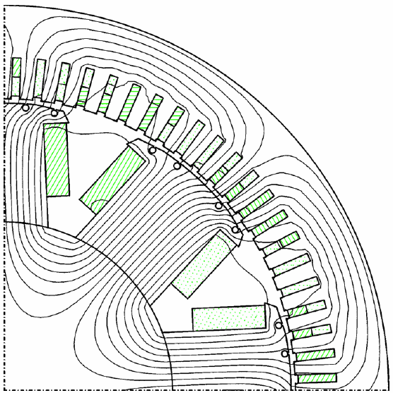
As you can see, most of the flux lines do not pass through the stator conductors. Instead, they prefer the magnetically less-reluctant iron.
And since only a little flux passes through the conductors, they don’t produce much torque either.
Indeed, in this particular case, only 5 % of the total torque is produced by the Lorentz force.
Paradoxically, a properly-derived equivalent circuit would still be able to predict the same torque with a good accuracy.
How can this be? I mean, we just demonstrated that the torque is not produced by the Lorentz force. How does using it still produce the correct result then?
Math to the Rescue
That was indeed the question my professor asked us the first time I was attending the aforementioned Numerical Methods course. He definitely did not serve the answer to us on a silver plate – it took me years to figure it out. Not that I was actively pursuing it – it simply to took some time and learning to come across all the necessary bits of information. Maths, mostly.
So, here goes.
To compute the torque with FEM, we need to know the flux density  in the air-gap. Once we have , the torque can be obtained e.g. with the Maxwell stress tensor or derived methods. We don’t even need to consider the entire air-gap. Any circle, or area between concentric circles, located fully in the air-gap is sufficient.
No matter where we compute it, the torque will be the same.
Let that sink in for a moment.
The torque cares not about how we compute it. Put another way, it is is fully oblivious to whatever happens elsewhere in the machine. Only that the air-gap flux density is correct.
And now we’re actually getting somewhere.
You see, this air-gap flux density can be obtained by solving the Maxwell’s equations in the air-gap. But they don’t care about what happens elsewhere in the machine, either. They only require some knowledge on what happens on the border of our air-gap domain. If these boundary conditions are correct, the air-gap field will be exactly the same as would be obtained from full-machine analysis.
How Equivalent Circuits Work
This equivalence principle is what makes equivalent circuits work. And here’s how we typically derive them.
First, we assume that the air-gap facing surfaces of both the stator and rotor are perfectly cylindrical. Additionally, both the stator and rotor iron are assumed to have an infinite magnetic permeability.
Next, the winding currents in the stator and rotor windings are represented by infinitely thin current sheets on said surfaces. If needed, we can represent permanent magnets in the same way, although the mathematics included are a bit more elaborate.
These currents then act as boundary conditions for the magnetic problem consisting only of the air-gap. By defining them correctly, we would get the exact same air-gap field as we have in the actual machine. That’s the beauty of boundary conditions.
However, we don’t usually go that far. Indeed, normally only the fundamental flux density harmonic produces useful torque. That means the part of the flux density that has as many poles as our machine and rotates at the same speed. Thus, it is sufficient to only replicate this part in our simplified model.
We can do this by using sinusoidally-distributed surface current densities, also varying sinusoidally in time. And, since our simplified purely-cylindrical geometry is quite close to the actual machine, we get their peak values easily from the machine and winding geometry.
The Torque, Finally
Now, the only remaining task is to compute the torque. We could use the same approach as with FEM, and use the Maxwell stress tensor to get the torque from the air-gap flux density.
However, we do have a simpler option available. Remember, we have the current densities bordering our equivalent problem domain. Hence, we can indeed use the Lorentz force formula, by simply integrating the surface current density and the radial flux density component across the stator surface. Or the rotor one, for that matter. The result will be the same, only differing in sign.
Conclusion
Phew, that was long and confusing. So, here’s a recap:
- Equivalent-circuit-based torque equations look like we are calculating the Lorentz force acting on the machine winding.
- We are not.
- Instead, we are calculating the Lorentz force acting on the boundary of a magnetically equivalent, simplified problem.
- Profit. Correct torque.
That was all. Next time, some cheesecakes.
-Antti
Check out EMDtool - Electric Motor Design toolbox for Matlab.
Need help with electric motor design or design software? Let's get in touch - satisfaction guaranteed!