Case Example: Triangulation and simulation quality.
Treat simulation software as a black box, and you might very well end in one. You know, if you, like, design and airplane and it crashes. Because you used a poor mesh and something gave in. Exactly the day you decided to be riding it. I’m the best storyteller in the recorded history…
Anyways, to the point:
Symmetry sectors in electrical machines
Electrical machines are often very nicely symmetrical. Stator slots and teeth are normally identical to each other, as are the poles of hydrogenerators, for example. Even more modern and exotic topologies, such as flux-swithing machines with permanent magnets, exhibit some level of symmetry.
For this reason, we rarely perform numerical analysis on the full machine. Instead, we extract something called a symmetry sector – something that is repeated identically around the full cross-section. You may have already seen the example below; I’ve used it in many of my SMEKlib posts after all.
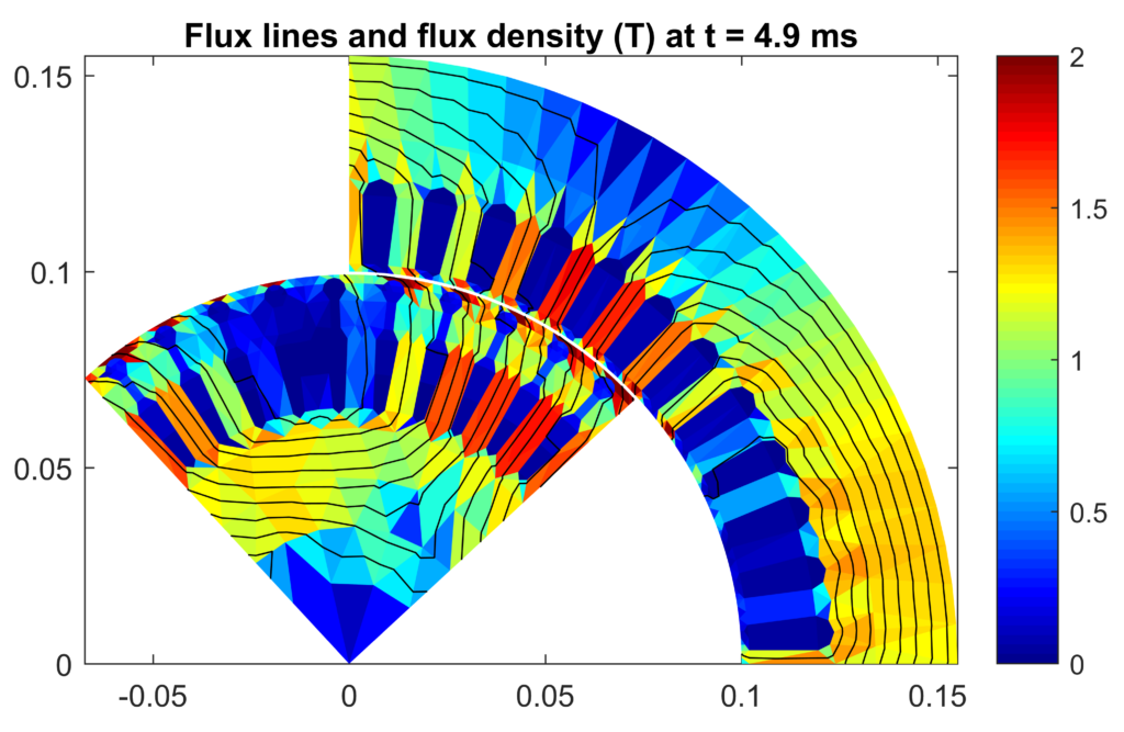
That there is a symmetry sector of a 37 kW induction motor. A quarter of the cross-section, to be exact.
Anyways, the idea of a symmetry sector is simple. Since the geometry of the sector is repeated around the cross-section, its electromagnetic behaviour will too. So, it is enough to analyse only the single sector, using periodic boundary conditions on the radial borders.
(By the way, if you are struggling with understanding or remembering boundary conditions, make sure to download my free guide ‘Boundary Conditions in Magnetic FEA‘).
Symmetry sectors are very nice for computational performance. Cutting the simulation domain in half of course cuts the number of unknowns to solve in half, too. And since solving a system of equations numerically pretty much always scales superlinearly, the computation time is more than halved.
When symmetry leads to weird things
However, weird things can occasionally happen because of this forced symmetry.
Below, you can see a part of a mesh. The grey parts denote the rotor surface, and a part of stator tooth number 1. The red air-gap triangulation is illustrated in red, and the thick red line denotes the symmetry sector.
As mentioned, only that upper part of the problem would normally be analysed. But, I simply replicated the symmetry sector mesh to cover the entire cross section. You’ll soon see why.

Normally, that mesh works nicely. You’ll get results that look nice and are close enough to measured results, at least considering all the other simplifications and uncertainties included in the simulation.
However, that does not mean there couldn’t be any error sources hidden underneath the surface.
Indeed, weird things become visible when you replace the iron parts by air. Below, you can see the vector potential at two points on the rotor surface, as a function of the rotor angle. The results have been obtained at no-load, so the potential is almost constant. You can also see the sixth harmonic, caused by the phase belts of the stator winding (i.e. the 5th and 7th spatial harmonics).
That makes perfect sense.
Weirdness
What does not make sense are the large peaks visible on the borders and in the middle. They simply should not be. The machine is not eccentric, or anything.

So, what’s causing this phenomenon? Periodic boundaries are not responsible – I checked. There were my first subject after all. But, it turned out the peaks were still there after replicating the sector mesh to cover the entire machine.
So faulty periodicity is not to blame.
Instead, the fault most likely lies in the structure of the mesh itself. Something special happens near tooth number 1.
It might be about the fact that we have two consecutive element edges in the radial direction.
Or, perhaps more likely, it’s about the tooth mesh. Tooth number 1 is the only one with an edge running across its centerline. That would also explain why the phenomenon is invisible in a normal simulation – the high permeability of iron effectively hides any minor perturbations caused by the mesh.
Why it matters
You might think that this observation is of no consequence. After all, it was made with a wholly unrealistic simulation – a machine without any iron.
However, the phenomenon is still there inside a realistic simulation, too. It’s just weaker.
What’s more important is realizing the fact that it can happen. Finite element analysis is numerical analysis after all, meaning the results will rarely be exact.
More often than not, there is some hidden source of error inside the simulation. Like we had here. That’s alright, it happens. However, what’s not alright is blindly trusting the simulation quality. At the very least, the possibility of error should be acknowledged, and prepared for. Even better would be doing some verification analysis, like what I did here.
That can spare you some nasty surprises in the future.
Have a simulation story to share? So…share!
-Antti
Check out EMDtool - Electric Motor Design toolbox for Matlab.
Need help with electric motor design or design software? Let's get in touch - satisfaction guaranteed!
Hi,
I remember I had a very similar problem with one PMSM model. The reason was the closest to the airgap and periodic boundary arc of half of a tooth. It was defined as a straight line segment and not as an arc. It was really difficult to spot visually as machine had large radius and quite many teeth, so the airgap arcs were all looked like small stright segments.
Another problem with boundaries had been faced by one my very experienced colleague. He used 2D FEM commercial software for squirrel-cage induction motor modelling. He modeled just one pole of the machine and he set anti-periodic boundary going through the middle of the rotor bar. The simulation went OK without any warning and the results were close to reality though the harmonic content in the gap was quite different from expected. Then we have rebuilt the model placing anti-periodic boundaries through rotor steel and results were much better then)
BR, Pavel
Hi Pavel, and thanks for the interesting examples! My two readers and I can now avoid making similar mistakes 😀
The latter one is especially interesting for me, I wonder what caused it. I mean I think the exact solution should stay the same whether or not you shift the symmetry sector by half a tooth-pitch or not. So, it’s probably somehow related to how the discretized problem behaves…maybe something about the tangential continuity of H which is not exactly satisfied with the A-formulation and also corresponds to a surface current density…
Interesting, interesting 😀
Hi Antti,
encountered the same problem a while ago. For some reasons I was extracting the magnetic vector potential, and extrapolating the H field from it, just in front of a tooth, cut in a half by the BC exactly as you show. This was not giving me what I expected.
I solved the issue upgrading to 3rd polynomial order approximation in the mesh. Much longer simulation time, but the values came out as I wanted them to be. Neither 2nd order elements where enough. The mesh was the same in all cases. I was using a commercial software.
Cheers,
Nicola
Hi Nicola, and thanks for another cool example!
I’m starting to suspect most mesh generators have a systematic flaw in this respect, at least when coarse meshes is used. Specifically, the teeth on the boundary are of course mirror-symmetric – they have been cut in half after all. However, towards the center of the symmetry sector, the slot pitch meshes gradually (or quite fast in fact) shift into approximate symmetry along the centerline of each slot, rather than tooth. This happens in both FCSMEK (our in-house software for those unaware) and gmsh.
I never thought this topic could turn out this interesting 😀